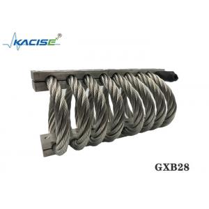
Product Description
The GXB28 Series Jack-up Isolators are housed coil wire rope isolators. Helical wire rope isolators are made of helical standard wire rope held with rugged metal retaining bars. This design provides excellent shock and vibration isolation. The wire rope isolator traditionally has been used in military/aerospace applications.
The Kacise Group has combined its military/aerospace technology into the GXB28 to produce a Jack-up Floor System that will attenuate shock with minimal displacement while providing inherent damping provided by the sliding friction between the strands of the wire rope. The wire rope isolator is an excellent candidate for large health clubs that have impact and shock from treadmills/exercise equipment and weight lifting activities.
The wire rope isolator is incorporated into a steel welded housing that is embedded into the concrete floor. The GXB28 has an access port that can interchange the isolator and features the Jack-up type adjustment system similar to the ANFF and ASFF isolators. The GXB28 can be manufactured for various floor thicknesses.
Product Size Chart
| Product number | High(mm) | Width(mm) | Product weight(kg) | Installation method | Hole size(mm) | Thread size(mm) | Counterbore taper |
| JGX-286-8-X-16860-A-S | 159 | ± 6.35 | 178 | 9.9 | A, B, C, D, E, S | Ø13.5 + 0.13- 0.38 | M12X1.75 | 90° |
Press Fit Test Data Sheet
| Curve number | Product number | Static load(N) | Maximum deformation (mm) | Vibration stiffness Kv kN/m | Impact stiffness Ks kN/m |
| 1 | JGX-286-8-X-16860-A-S | 8450 | 74.9 | 1270 | 469 |
45° Inclined Press Fitting Load Test Data Sheet
| Curve number | Product number | Static load(N) | Maximum deformation (mm) | Vibration stiffness Kv kN/m | Impact stiffness Ks kN/m |
| 1 | JGX-286-8-X-16860-A-S | 6010 | 105.4 | 718 | 235 |
Shear Rolling Load Test Data Sheet
| Curve number | Product number | Static load(N) | Maximum deformation (mm) | Vibration stiffness Kv kN/m | Impact stiffness Ks kN/m |
| 1 | JGX-286-8-X-16860-A-S | 2890 | 77.5 | 291 | 291 |

Wire rope vibration isolators have the following advantages:
• Wide range of available sizes permits attachment to almost any machinery or enclosure regardless of weight.
• Compact, low profile design and the ability to attenuate heavy shock loads with minimum deflection allows use where space is at a premium.
• Three-plane, all-axis isolation means that the equipment is free to move in any direction – vertically, horizontally and laterally.
• Custom winding, loop count and mounting features are available to meet specific requirements.
• Special cable materials (galvanized steel and other stainless steel alloys), special bar materials (stainless steel, titanium finish platings) and special mounting configurations (inserts, thread types, clearance holes) to name just a few, are available upon request.
Product structure diagram
Guide for installation of wire rope isolator
1. Before installation, please carefully check whether the mounting hole matches the mounting hole of the vibration isolator, such as whether the thread is the same, etc.
2, the installation hole is clean, there is no burr, rust, damage and other defects.
3. Since the vibration isolator is an elastic component, it needs a little movable space when working. Before installation, please carefully check whether there is any equipment affecting installation in the installation part and whether the movable space of the vibration isolator is enough. Please check whether the vibration isolator is in good condition and has no defects before installation.
4. Prepare a suitable screwdriver and crowbar.
5, first install the isolator to heavy equipment or fixed equipment, installation screws do not need to tighten, so that the isolator can be slightly active.
6. Install the connecting device on the other side of the vibration isolator. If the mounting hole is slightly misaligned, you can move the vibration isolator or use a crowbar to align the mounting hole of the vibration isolator with the mounting hole of the equipment, and then screw the fixing screw.
7. After fixing the device position, tighten all the fixing screws.
Application